(RD24) RD24 - Power Dist and ESCs
Published: Sat Apr 14 2012
So first off, for this session I cracked open 6 new ESCs.

Then I soldered 24cm Silicone wire extensions on the ESCs so I can leave them in the main body and extend them out to the motors.

The female bullets on the ends and shrink tube on splices and connectors, Next was to solder them to my new cheap distribution board, which I am really liking, I got them here:
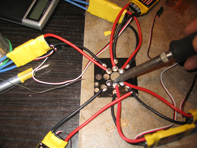
All the ESCs are now soldered to teh PDB

All Extensions are now on.

The wires are coded such that each middle wire is a different color, so the ESC to motor wiring goes
A1 - R B R
A2 - B R B
B1 - B R B
B2 - R B R
C1 - R B R
C2 - B R B
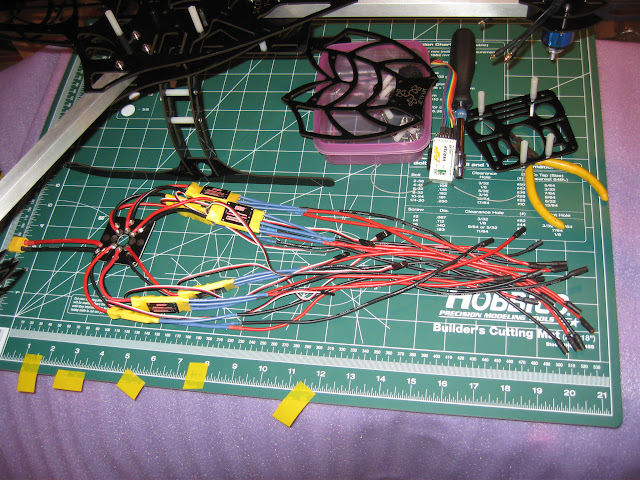
This simplifies the process of reversing direction on a motor by having one wire a different color, so swapping any black and red reverses and is less confusing, also when looking at the motors, one motors wil have two reds and the other motor will have 2 blacks, making it easier to figure out which ESC connects to which motors when its all wired up.
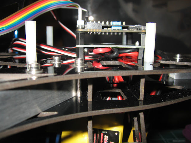
Then I removed the FC and mounted the PDB instead,

it was tough feeding everything down into the frame, but I got it in there, then put the FC on top.

However this is NOT going to work, as there is not enough room to mount the next deck and still pliug the ESCs and RX on the FC, so I will have to try recucing the space between FC and the PDB. Also there is a minor alignment problem as you can see the standoff on the bottom right is crooked.
I will be taking a break on this model for a bit, since I cant fly it outside right now anyhow and will be finishing up the Nano copters, RD22 and RD23.